Air Coil Winding

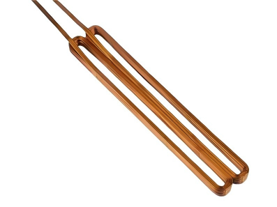
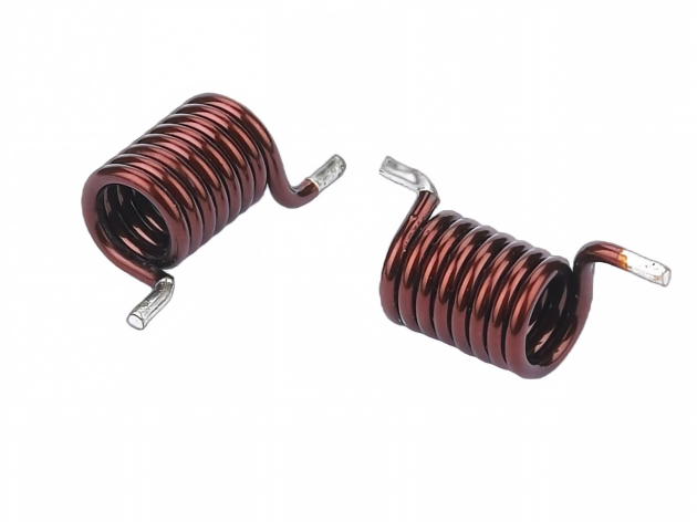
Air coil winding is a precision manufacturing process that shapes bare wire into self-supporting electromagnetic coils without a magnetic core. Unlike bobbin-wound coils, air coils rely solely on the wire’s own geometry to maintain their shape, making them ideal for high-frequency applications where core losses and saturation must be eliminated.

At Mach Prototype, we manufacture custom air coils to your exact specifications — from single prototype runs to low-volume production. Our winding process delivers consistent dimensional accuracy, tight pitch control, and reliable electrical performance across every batch.

Winding Types and Material


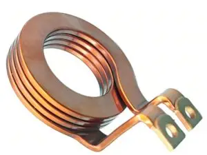
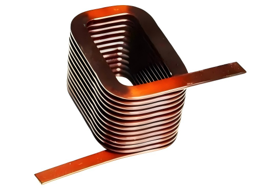
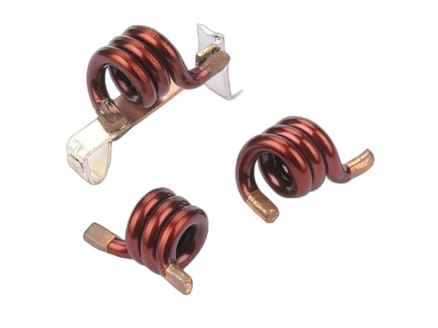
Flat Wire (Rectangular)

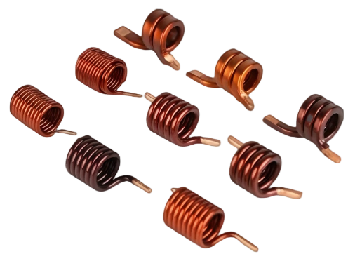
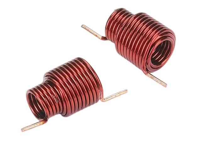
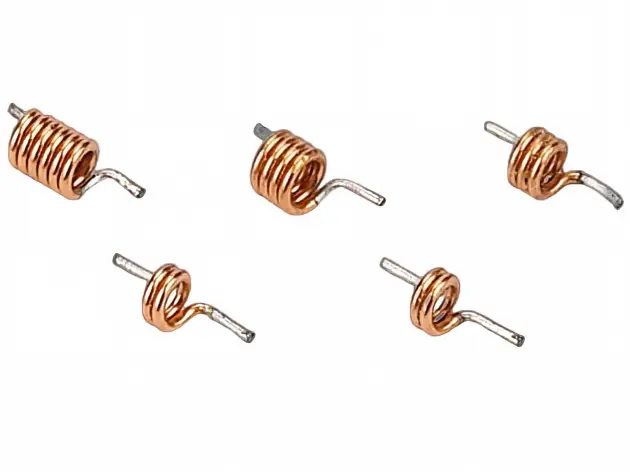
Round Wire

Rectangular Coils

High copper fill factor, low DC resistance, excellent heat dissipation. Ideal for high-current planar assemblies.

Versatile and cost-effective, easy to terminate, wide gauge range. The standard choice for general-purpose PCB-mount coils.


Typical: EV onboard chargers, DC-DC converters, power inductors

Typical: RFID antennas, proximity sensors, general inductors

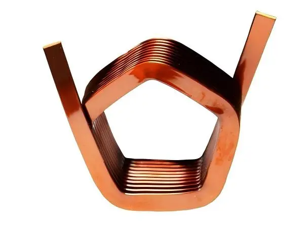
Triangle Coils

High current density in a compact angular footprint; specialized field distribution for space-constrained power modules.

Flexible angular profiles for non-standard layouts; lightweight and easy to form into custom geometries.


Typical: Compact power modules, high-density sensor arrays

Typical: Space-constrained sensors, custom antennas, precision detection coils

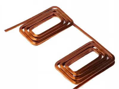
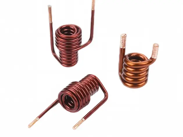
Linked Coils

Multi-section interconnected arrays with high current handling; complex field shaping with minimal parasitic loss.

Interconnected or multi-coil arrays with flexible routing; easy to customize section count and spacing.


Typical: Multi-phase power systems, industrial induction heating, complex field generators

Typical: Multi-channel sensor arrays, RFID matrix antennas, gradient field coils

Size and Tolerance


Size(Length*width,Min)

Size(Length*width,Max)

Tolerance

Rectangular Air Coil

2mm*2mm

120mm*40mm

ISO2768-m

Round Air Coil

Diameter 2mm

Diameter 50mm

ISO2768-m

Linked Rectangular Coil

2mm*2mm

50mm*40mm

ISO2768-C

Linked Round Coil

Diameter 2mm

Diameter 50mm

ISO2768-C

Finish & Additional Manufacturing

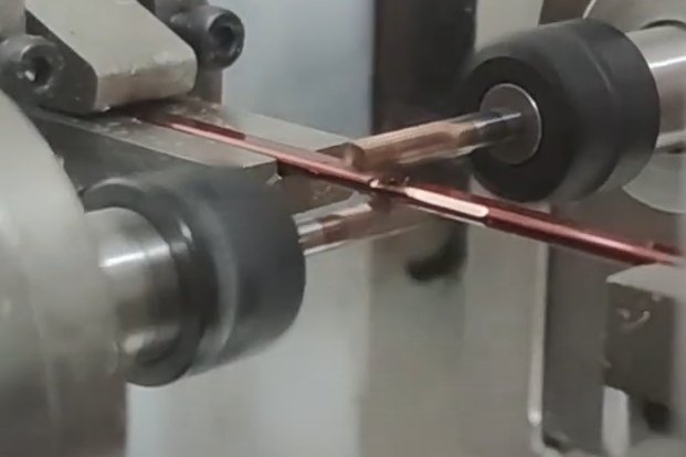
Peel removing

Peel removing precisely strips insulation from the wire ends, exposing clean conductor without damage. This establishes a reliable electrical contact surface while preserving insulation integrity across the coil.

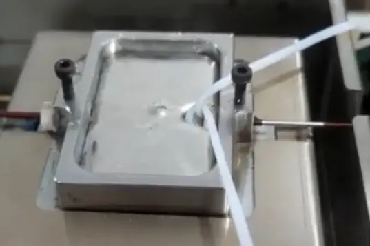
Tin coating

Tin coating follows immediately, sealing the exposed conductor with a uniform tin layer to prevent oxidation and guarantee consistent solderability.

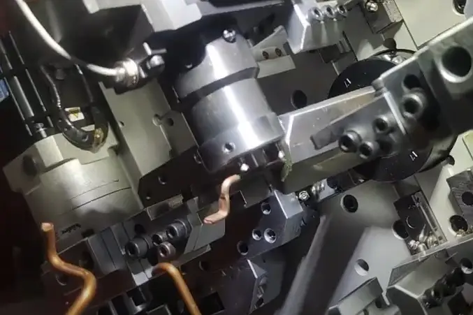
Wire ends bending

Wire ends bending forms the tinned leads to your specified geometry — right-angle, SMD gull-wing, through-hole, or custom footprint. Precision tooling ensures the coil aligns with your pad layout and sits flat through reflow without positional drift.

Wire ends stamping

Wire ends stamping completes the process, flattening or coining leads into SMD pads, press-fit pins, or tab terminals. This creates a robust mechanical interface with defined contact area, enabling high-volume automated assembly and eliminating hand-soldering variation.

Air Coil for Different Industries

Air coils are uniquely versatile — their core-free design eliminates saturation and core losses, making them indispensable across industries where precision, reliability, and high-frequency performance matter. From the harsh under-hood environment of an electric vehicle to the sterile confines of a medical implant, our air coils are engineered to perform where other components cannot.

✔Aerospace
✔Medical Devices
✔Automotive
✔Robotics
✔Electronics
✔Communication
✔Semiconductor
✔New Energy
✔Consumer Products

Design Tips for Air Coils

Mechanical design determines whether a coil fits your assembly, survives its environment, and performs consistently at volume. Consider these factors before finalizing your drawing.

  • Radii  of inner fillets ≥wire width—At every internal bend and corner transition, the fillet radius must be at least equal to the wire width (or wire diameter for round wire). A tighter radius compresses the conductor on the inside of the bend and stretches the insulation on the outside, causing enamel cracking, conductor work-hardening, and premature fatigue failure. This is especially critical for flat-wire coils, where the wide cross-section amplifies bending stress.
  • Inner distance of coil should be twice than wire width—The inner dimension of the coil should be no less than two times the wire width (flat wire). This was decided by the machining process and tooling.
  • Specify lead forming before winding — Bend radius, lead pitch, standoff height, and SMD pad footprint should be defined on the original drawing. Changing lead geometry after winding tooling is built requires re-fixturing and can introduce dimensional variation.


  • Define the mounting method — PCB surface-mount, through-hole, adhesive-bonded, clip-mounted, and fixture-held coils each require different lead forming and base geometry. The mounting method dictates whether leads need flat stamped pads, bent gull-wings, or straight through-hole pins.
  • Account for spring-back and set — Wire retains memory from the winding process. Multi-layer and high-turn-count coils may exhibit slight dimensional drift after removal from the mandrel. We compensate for this in winding, but your drawing should specify whether dimensions are measured free-state or under fixture load.
  • Plan clearance around the coil — Air coils have no core to shield them mechanically. Specify the minimum clearance to adjacent components, especially in high-vibration environments where the coil may flex. If the winding body needs structural support, consider an adhesive bond or a retaining feature in your housing.
  • Match insulation to assembly stress — Enamel thickness and insulation type affect both outer diameter and mechanical robustness. If the coil will be handled, potted, or subjected to reflow thermal cycling, specify a heavier insulation build or a secondary coating to prevent wire-to-wire shorts during assembly.